Chebyshev Filters: applications and code examples
This article discusses the advantages and disadvantages of the Chebyshev filter, including code examples in ASN Filterscript.
Chebyshev Type II filters have flat passbands (no ripple), making them a good choice for DC and low frequency measurement applications, such as bridge sensors (e.g. loadcells). However, this desirable property comes at the expense of wider transition bands, resulting in low passband to stopband transition (slow roll-off). The Chebyshev Type I roll-off faster but have passband ripple and very non-linear passband phase characteristics.
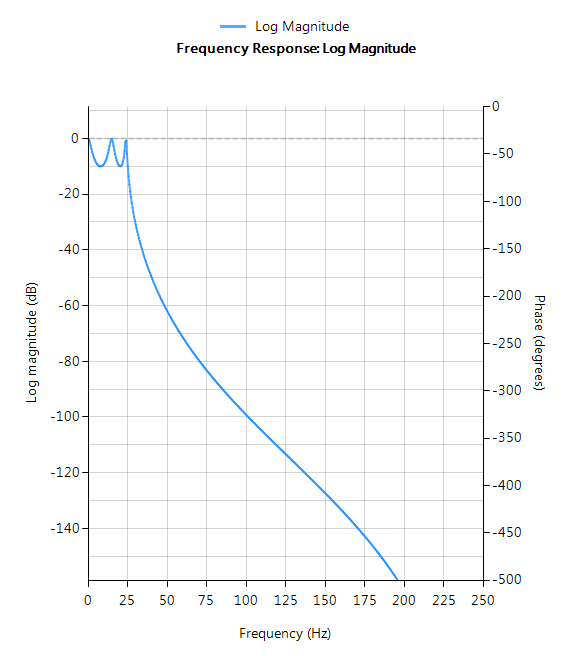
Chebyshev Type I
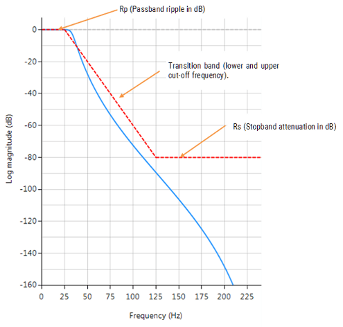
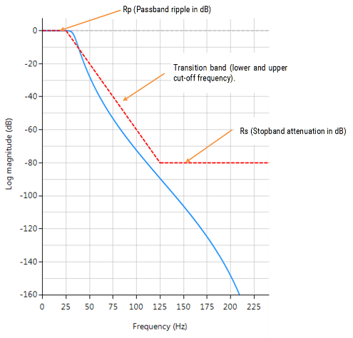
Chebyshev Type I filters are equiripple in the passband and monotonic in the stopband. As such, Type I filters roll off faster than Chebyshev Type II and Butterworth filters, but at the expense of greater passband ripple.
Filter characteristics
- Passband ripple
- Maximally flat stopband
- Faster roll-off than Butterworth and Chebyshev Type II
- Good compromise between Elliptic and Butterworth
Chebyshev Type II
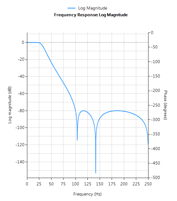
Chebyshev Type II filters are monotonic in the passband and equiripple in the stopband making them a good choice for bridge sensor applications. Although filters designed using the Type II method are slower to roll-off than those designed with the Chebyshev Type I method, the roll-off is faster than those designed with the Butterworth method.
Filter characteristics
- Maximally flat passband
- Faster roll-off than Butterworth
- Slower roll-off than Chebyshev Type I
- Good choice for DC measurement applications
Read more about other IIR filters in IIR filter design: a practical guide
Syntax Chebyshev Filters
An example in ASN Filterscript now follows.
Syntax Chebyshev I
Syntax
Hd = cheby1 (Order, Frequencies, Rp, Rs, Type, DFormat)
Description
Classic IIR Chebyshev Type I filter design
- Maximally flat stopband
- Faster roll off (passband to stopband transition) than Butterworth
Hd = cheby1 (Order, Frequencies, Rp, Rs, Type, DFormat)
Order: may be specified up to 20 (professional) and up to 10 (educational) edition. Setting the Order to 0, enables the automatic order determination algorithm.
Frequencies: lowpass and highpass filters have one transition band, and in as such require two frequencies (i.e. lower and upper cut-off frequencies of the transition band). For bandpass and bandstop filters, four frequencies are required (i.e. two transition bands). All frequencies must be ascending in order and < Nyquist (see the example below). Rp: Passband ripple in dB. This is somewhat of a misnomer, as the Butterworth filter has a maximally flat passband. A good default value is 0.001dB, but increasing this value will affect the position of the filter’s lower cut-off frequency.
Rs: Stopband attenuation in dB. This is somewhat of a misnomer, as the Butterworth filter has a maximally flat stopband, which means that the stopband attenuation (assuming the correct filter order is specified) will be ≥ stopband specification.
Type: The Butterworth method facilitates the design of lowpass, highpass, bandpass and bandstop filters respectively.
Hd: the Butterworth method designs an IIR Butterworth filter based on the entered specifications and places the transfer function (i.e. numerator, denominator, gain) into a digital filter object, Hd. The digital filter object can then be combined with other methods if so required. For a digital filter object, Hd, calling getnum(Hd), getden(Hd) and getgain(Hd) will extract the numerator, denominator and gain coefficients respectively – see below.
DFormat: allows you to specify the display format of resulting digital filter object.
symbolic |
Display a symbolic representation of the filter object. If the order > 10, the symbolic display option will be overridden and set to numeric. |
numeric |
Display a matrix representation of the filter object |
void |
Create a filter object, but do not display output |
Example
[code lang=”java”]
ClearH1; // clear primary filter from cascade
ShowH2DesignMarkers; // show DM on chart
Main()
Rp=1.4;
Rs=80;
F={50,120};
Hd=cheby1(0,F,Rp,Rs,”lowpass”,”symbolic”);
F={50,80,100,120};
Hd=cheby1(0,F,Rp,Rs,”bandpass”,”symbolic”);
Num = getnum(Hd); // define numerator coefficients
Den = getden(Hd); // define denominator coefficients
Gain = getgain(Hd); // define gain
[/code]
Syntax Chebyshev II
Syntax
Hd = cheby2 (Order, Frequencies, Rp, Rs, Type, DFormat)
Description
Classic IIR Chebyshev Type II filter design
- Maximally flat passband
- Slower roll off (passband to stopband transition) than Chebyshev Type I
Hd = cheby2 (Order, Frequencies, Rp, Rs, Type, DFormat)
Order: may be specified up to 20 (professional) and up to 10 (educational) edition. Setting the Order to 0, enables the automatic order determination algorithm.
Frequencies: lowpass and highpass filters have one transition band, and in as such require two frequencies (i.e. lower and upper cut-off frequencies of the transition band). For bandpass and bandstop filters, four frequencies are required (i.e. two transition bands). All frequencies must be ascending in order and < Nyquist (see the example below). Rp: Passband ripple in dB. This is somewhat of a misnomer, as the Chebyshev Type II filter has a maximally flat passband. A good default value is 0.001dB, but increasing this value will affect the position of the filter’s lower cut-off frequency.
Rs: Stopband attenuation in dB.
Type: The Chebyshev Type II method facilitates the design of lowpass, highpass, bandpass and bandstop filters respectively.
Hd: the cheby2 method designs an IIR Chebyshev Type II filter based on the entered specifications and places the transfer function (i.e. numerator, denominator, gain) into a digital filter object, Hd. The digital filter object can then be combined with other methods if so required. For a digital filter object, Hd, calling getnum(Hd), getden(Hd) and getgain(Hd) will extract the numerator, denominator and gain coefficients respectively – see below.
DFormat: allows you to specify the display format of resulting digital filter object.
symbolic |
Display a symbolic representation of the filter object. If the order > 10, the symbolic display option will be overridden and set to numeric |
numeric |
Display a matrix representation of the filter object |
void |
Create a filter object, but do not display output |
Examples
[code lang=”java”]
ClearH1; // clear primary filter from cascade
ShowH2DesignMarkers; // show DM on chart
Main()
Rp=1;
Rs=80;
F={50,120};
Hd=cheby2(0,F,Rp,Rs,”lowpass”,”symbolic”);
F={50,80,100,120};
Hd=cheby2(0,F,Rp,Rs,”bandpass”,”symbolic”);
Num = getnum(Hd); // define numerator coefficients
Den = getden(Hd); // define denominator coefficients
Gain = getgain(Hd); // define gain
[/code]

