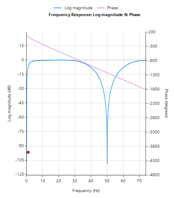
FIR notch filter from a lowpass filter
Syntax
Hd = firlp2notch(Hd,DFormat)
Description
Designs an FIR notch filter from a lowpass filter by computing the difference between the prototype lowpass filter and its amplitude complementary, i.e. \( \displaystyle{H_{BSF}(z)=2H_{LPF}(z)-1.}\)
The resulting bandstop filter (BSF) or notch filter has linear phase (odd length), but a 180-degree phase shift at the notch frequency. This means that all frequencies > notch frequency will be shifted by 180 degrees. For biomedical applications, this excess phase shift is undesirable and may be overcome by cascading two identical filters, such that the phase shift is 360 degrees. The augument() function should be used for achieving this, as shown below in the example.
Hd: the firlp2notch method designs an FIR notch (bandstop) filter based on the entered specifications and places the transfer function (i.e. numerator and gain) into a digital filter object, Hd. For even length filters, the method will automatically add an extra coefficient at the centre of the impulse response in order to make it odd in length. The digital filter object can then be combined with other methods if so required. For a digital filter object, Hd, calling getnum(Hd) ) and getgain(Hd) will extract the numerator and gain coefficients respectively – see below.
DFormat: allows you to specify the display format of resulting digital filter object.
symbolic |
Display a symbolic representation of the filter object. If the order > 10, the symbolic display option will be overridden and set to numeric. |
numeric |
Display a matrix representation of the filter object |
void |
Create a filter object, but do not display output |
Examples
[code lang=”java”]interface F = {10,400,2,44}; // frequency spec (2 bands for bandstop)
interface TW ={1,40,2,12}; // Band transition width
interface N = {20,300,1,36};
Main() // main loop
Freq={F,F+TW}; // frequency specification
Hd=firwin(N,Freq,”hanning”,”lowpass”,”numeric”);
Hd=firlp2notch(Hd,”void”);
Hd=augment(Hd,Hd,”void”); // compensate for 180 phase shift by cascading a second filter
Num=getnum(Hd);
Den=getden(Hd);
Gain=getgain(Hd);
[/code]
Biomedical filtering application
The firlp2notch function can used in conjunction with dcremover function in order to build an ECG biomedical filtering cascade with linear phase around the notch cut-off frequency. Notice that the two filters are split up into the H1 and H2 filters respectively, and may therefore be optimised independently to each other.
[code lang=”java”]
// Biomedical HPF + FIR notch filter.
// This notch filter removes 50/60Hz power line interference while
// maintaining linear phase around the notch cut-off frequency. The DC offset
// and low frequencies are removed via the H1 IIR HPF.
//
// Copyright Advanced Solutions Nederland 2021
// Revision: 1.00
interface F = {10,400,2,44}; // frequency spec (2 bands for bandstop)
interface TW ={1,40,2,12}; // Band transition width
interface R ={10,80,5,40}; // Band transition width
interface N = {20,300,1,36};
Main() // main loop
Freq={F,F+TW}; // frequency specification
//Hd=firkaiser(Freq*fsunits,R,”lowpass”,”numeric”);
Hd=firwin(N,Freq,”hanning”,”lowpass”,”numeric”);
Hd=firlp2notch(Hd,”void”);
Hd=augment(Hd,Hd,”void”); // compensate for 180 phase shift by cascading a second filter
Hd1=dcremover(2,”void”);
Num=getnum(Hd);
Den=getden(Hd);
Gain=getgain(Hd);
H1Num=getnum(Hd1);
H1Den=getden(Hd1);
H1Gain=getgain(Hd1);
[/code]
Designers are also referred to the following application note that discusses the design and implementation of the Pan-Tompkins filter cascade for QRS complex detection in ECG signals.
See also:
movaver / firwin / firarb / firkaiser / firgauss / firlp2notch / savgolay


