All-pass filters
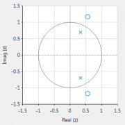
All-pass filters provide a simple way of altering/improving the phase response of an IIR without affecting its magnitude response. As such, they are commonly referred to as phase equalisers and have found particular use in digital audio applications. In its simplest form, a filter can be constructed from a first order transfer function, i.e., \( A(z)=\Large{\frac{r+z^{-1}}{1+r z^{-1}}} \, \, \normalsize{; r<1} \) Analysing \(\small A(z)\), notice that the pole and zero lie on the real z-plane axis and that the pole at radius \(\small r\) has a zero at radius \(\small 1/r\), such that the poles and zeros are reciprocals of another. This property is key to the all-pass filter concept, as we will now see by expanding the concept further to a second order all-pass filter: \( A(z)=\Large\frac{r^2-2rcos \left( \frac{2\pi f_c}{fs}\right) z^{-1}+z^{-2}}{1-2rcos \left( \frac{2\pi f_c}{fs}\right)z^{-1}+r^2 z^{-2}} \) Where, \(\small f_c\) is the centre frequency, \(\small r\) is radius of the poles and An All-pass filter may be implemented in ASN FilterScript as follows: interface radius = {0,2,0.01,0.5}; // radius value Main() [/code] \(\small f_s\) is the sampling frequency. Notice how the numerator and denominator coefficients are arranged as a mirror image pair of one another. The mirror image property is what gives the all-pass filter its desirable property, namely allowing the designer to alter the phase response while keeping the magnitude response constant or flat over the complete frequency spectrum.
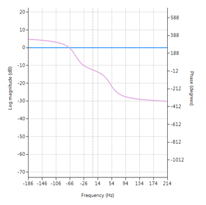
 Frequency response of all-pass filter:
Notice the constant magnitude spectrum (shown in blue). Implementation
[code language=”java”]
ClearH1; // clear primary filter from cascade
interface fc = {0,fs/2,1,fs/10}; // frequency value
Num = {radius^2,-2*radius*cos(Twopi*fc/fs),1};
Den = reverse(Num); // mirror image of Num
Gain = 1;
For a detailed discussion on IIR filter phase equalisation, and the ASN Filter designer’s APF (all-pass filter) design tool, please refer to the following article.


